www.leguman.ht.st
| HEAD LOSSES |
PUMPS |
CONDUCTION |
©
2001 - 2002.
|
| previous | ||
|
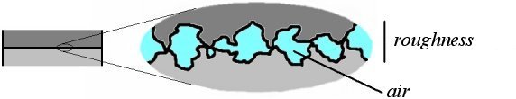
Contact resistance With these two contacting plates, the formula used previously supposes
they are in perfect contact, which would be the case
if the two surfaces which make the interface between the two plates
were perfectly flat and smooth.
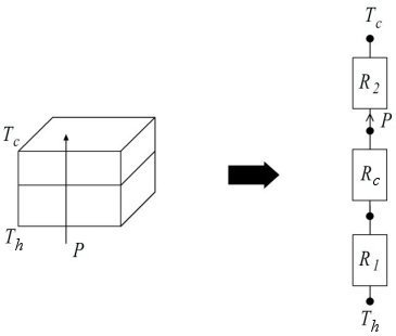
The effect of roughness is very important; in general the real surface contact area is never higher than 2% of the interface surface area, yes 2%!!! This leaves enough places for micro-cavities filled with air, which has a very bad thermal conductivity ( see the table of conductivities at the beginning ). All this thickness ( 0.5 - 60 mm for flat surfaces ) consisting of roughness and air gaps form a thin layer which will less conduct heat, this translates into contact resistance Rc which will depend of :
This resistance is added to the thermal circuit :
The means to reduce the contact resistance are well known :
|
||
| previous |